- 您现在的位置:买卖IC网 > Sheet目录221 > DPM950S (Martel Electronics)3.5 DIGIT 200MVDC LED BACKLIT
DPM 950
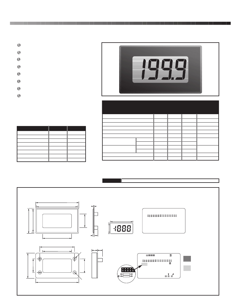
3 ? Digit LCD Module
Very low current consumption results in a long battery life and makes the DPM 950 ideal for portable equipment. For low light viewing,
a long life LED backlight is fitted. The meter is housed in a robust carrier which can be bolted in place or panel mounted using the bezel,
window and clips provided.
19mm (0.75“) Digit Height
IDC Interface
Auto-zero
Auto-polarity
200mV d.c. Full Scale Reading (F.S.R.)
LED Backlight
Single Rail Version
Alarm Annunciator
Stock Number
SCALING
Two resistors Ra and Rb may be fitted in order to alter the
full scale reading (F.S.R.) of the meter - see table.
Standard Meter
Single Rail Version
Specification
Min.
Typ.
Max.
DPM 950
DPM 950S
Unit
The meter will need re-calibration.
Accuracy (overall error) ** 0.05
Linearity
0.1
±1
% (±1 count)
count
Required F.S.R.
2V Note
20V Note
200V Note
2kV Note
200 μ A
2mA
20mA
200mA
Ra
910k
1M
1M
1M
LINK
LINK
LINK
LINK
Rb
100k
10k
1k
100R
1k
100R
10R
1R
Sample rate 3
Operating temperature range 0
Temperature s tability 100
Supply voltage DPM 950 7.5 9
(V+ to V-) DPM 950S 3.5 5
Supply current DPM 950 150
(not including backlight) DPM 950S 500
Backlight current * 50
Input leakage current (Vin = 0V) 1
* Supply voltage 5V nom.
50
14
6.5
10
samples/sec
°C
ppm/°C
V
μ A
mA
pA
NOTE
Ensure that Link 10 is open if fitting Ra.
** To ensure maximum accuracy, re-calibrate periodically.
CONNECTOR SOURCING GUIDE
DIMENSIONS All dimensions in mm (inches)
76.0 (2.99)
METHOD
Cable Mounting IDC Supplied With Product
72.5 (2.85)
a
a. 1.0 (0.04)
b. 2.0 (0.08)
c. 6.5 (0.26)
d. 11.5 (0.45)
e. 9.5 (0.37)
51 (2.01)
REAR
VIEW
51.0 (2.01)
b c
Display in Test Mode
Panel cut-out 72 x 40 (2.83 x 1.57)
Maximum panel thickness 3mm (0.12).
61.5 (2.42)
51.0 (2.01)
?5.7
d
e
(0.22)
2 34 1
11
ON BOARD
SOLDER LINKS
Ra
Rb
12
SCALING RESISTORS
CAL
Ra
Rb
REAR
VIEW
DP1
DP2
DP3
71.5 (2.81)
?3.0
(0.12)
发布紧急采购,3分钟左右您将得到回复。
相关PDF资料
DPM970
METER DPM LCD 200MV IN
DPT-200
TIP REPLACEMNT FOR DP-200
DRP012V015W1AZ
POWER SUPPLY DIN RAIL 15W 12VDC
DRP024V120W1BA
POWER MODULE 24V 120W 1PH
DRP024V240W1BA
AC/DC CONVERTER 24V 10A 240W DIN
DS1217M-L04
RAM READ/WRITE NV LO LEAK 4MEG
DS1904L-F5#
IBUTTON RTC F5 MICROCAN
DS1920-F5+
IBUTTON TEMPERATURE F5
相关代理商/技术参数
DPM970
功能描述:METER DPM LCD 200MV IN RoHS:是 类别:工业控制,仪表 >> 仪表 - 面板,数字 系列:900 标准包装:12 系列:* 其它名称:Q7072030
DPMB9058
制造商:未知厂家 制造商全称:未知厂家 功能描述:GaAs Bi-Phase Modulator
DPMF8P12-1J
功能描述:薄膜电容器 .012UF 800V 5% RoHS:否 制造商:Cornell Dubilier 产品类型:High Frequency 电介质:Polypropylene (PP) 电容:0.012 uF 容差:5 % 电压额定值:800 V 系列:DPM 工作温度范围:- 55 C to + 105 C 端接类型:Radial 引线间隔:
DPMF8P12-1J-F
功能描述:薄膜电容器 .012UF 800V 5% RoHS:否 制造商:Cornell Dubilier 产品类型: 电介质:Polyester 电容:0.047 uF 容差:10 % 电压额定值:100 V 系列:225P 工作温度范围:- 55 C to + 85 C 端接类型:Radial 引线间隔:9.5 mm
DPMINI10
制造商:SR COMPONENTS 功能描述: 制造商:SR Components Inc 功能描述:
DPMINI3
制造商:SR COMPONENTS 功能描述: 制造商:SR Components Inc 功能描述:
DPMINI6
制造商:SR COMPONENTS 功能描述: 制造商:SR Components Inc 功能描述:
DPMINIMVGAF
制造商:SR COMPONENTS 功能描述: 制造商:SR Components Inc 功能描述:
